
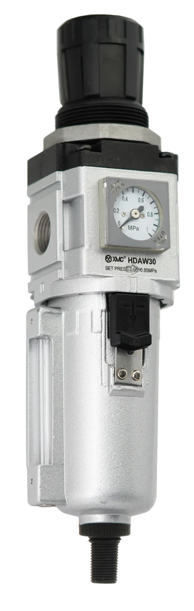
Central treatment and point-of-use preparation are different responsibilities within the same air path. Define the shared supply condition, then map the air quality, operating pressure and lubrication permission required at each user. Allocate any additional treatment and verification to named boundaries. Select HA or HDA components only after that map is agreed; neither family name determines its location, and one central FRL does not by itself establish compliance at every machine.
Compare responsibilities before comparing the number of FRLs
Central treatment serves an agreed shared supply boundary; point-of-use treatment addresses the requirements of a particular branch or consuming device. They need not be competing whole-system choices. Parker’s guidance separates the air-quality requirement leaving the compressor room from requirements at each point of use. It recommends reviewing treatment before distribution and at critical applications. [1] The purchasing question is therefore which requirements can share a treatment duty and which remain specific to one user. A count of filters or regulators cannot answer that question.
A hypothetical three-branch requirement map
Assume a project brief contains three different requirements: Machine A prohibits added lubricant, Tool B requires external oil-mist lubrication, and Process C has a separate air-quality specification that has not yet been supplied. These are hypothetical inputs, not claims about a customer installation or universal rules for those equipment types. The topology for discussion is an existing shared treatment boundary S0, followed by distribution that divides into A, B and C. No sizes, pressures, treatment sequence or isolation hardware are selected by this example.
| Boundary | Requirement source in this example | Duty to resolve | Evidence needed before selection |
|---|---|---|---|
| S0: shared supply handover | Plant brief; actual delivered condition still to be verified | Define the condition offered to all three downstream branches. | Current treatment record, supply condition, measurement location and responsible party. |
| A1: Machine A inlet | Hypothetical manual prohibits added lubricant | Preserve the stated no-added-oil requirement and review any additional local treatment. | Actual manual, inlet pressure/demand and required particle, water and oil limits. |
| B1: Tool B supply | Hypothetical manual requires external oil-mist lubrication | Review dedicated lubrication for the approved user, separate from A and C requirements. | Actual lubrication instructions, selected oil and lubricator operating conditions. |
| C1: Process C inlet | Application air-quality document not yet available | Keep treatment selection open; do not infer purity from A, B or the shared station. | Complete application specification, required measurement point and acceptance method. |
Keep intentional oil addition inside the approved user’s requirement
In this example, adding a lubricator on the shared path before the split would also introduce oil toward users A and C. That conflicts with the stated requirement for A and leaves C unresolved. Ask the designer to place any intentional lubrication within the approved branch arrangement and check the whole path. Festo recommends locating a lubricator near the consuming device where possible to avoid unnecessarily carrying oil through the system. [3] This is a general principle, not a connection drawing for XMC products. A downstream mist separator is not an automatic permission to lubricate a shared line or a guarantee that an added-oil requirement has been reversed.
Allocate extra treatment without duplicating an unexplained stage
For each proposed local stage, state which requirement it addresses and what upstream condition it needs. Identify the evidence that the existing shared treatment does or does not provide. If the requirement concerns water vapour, oil content or particles, keep those fields separate and use the relevant treatment review. Do not add another identical filter at every machine merely because a box on the drawing is labelled FRL. Equally, do not remove local treatment solely because central equipment exists. The decision must close a documented requirement at the consuming boundary.
Choose XMC functions after the boundary decisions
The XMC catalogue identifies HAF filtration, HAR regulation and HAL lubrication as separate large-port component functions. The HDA pages distinguish HDAF filtration, HDAR regulation, HDAL lubrication and combined HDAW filtration/regulation; HDAFM is a separate mist-separator family. [4-7] These are candidate functions, not a rule that HA belongs centrally and HDA belongs at a machine. Match the proposed unit and arrangement to its duty, complete model, connection, operating data and service access. An HDAW label does not establish a complete air-quality class, and the HDAFM selection does not supply a dryer dew-point guarantee.
Assign service and acceptance responsibility at each handover
For the proposed arrangement, identify who checks the shared treatment, who checks each local unit and who accepts the delivered condition. Mark which users could be affected by maintenance or a change of route. A local treatment position does not itself establish independent isolation; the machine’s approved procedures govern service. Keep a change to a shared stage, bypass route or lubrication arrangement visible to the responsible downstream users. The worksheet below is a suggested project record, not a mandated maintenance interval or a complete commissioning procedure.
| Record field | Shared handover S0 | Local handover A1, B1 or C1 |
|---|---|---|
| Specification and owner | Name the plant-air requirement and the person responsible for supplying it. | Attach the actual equipment/application requirement and its owner. |
| Treatment and route | Record existing/proposed shared units and the normal air route. | Record branch-specific units, lubrication permission and the route to the consuming point. |
| Verification | State the agreed observation or test point, operating conditions, method and evidence. | State how compliance is checked at the required user boundary; do not inherit an unrelated upstream result. |
| Service and change control | Identify service responsibility and users to notify when the shared arrangement changes. | Identify local checks, applicable service instructions and when a plant-air change needs review. |
Send a requirement map with the quotation request
Send the boundary drawing and both worksheets together. Attach the actual machine air-quality and lubrication documents, supply and demand information, current models and proposed purchasing scope. Label assumed, measured and unknown inputs. Ask XMC to review the relevant component functions and arrangement, while the plant-air and application suppliers close their own specification and acceptance items. Where Process C’s requirement remains missing, preserve that dependency rather than borrowing a purity class or selecting its treatment from another branch.
Catalogue and technical references
The branch map and responsibility worksheet are illustrative purchasing tools. They do not specify a complete engineered system, tested layout or measured energy saving. External guidance supports general distribution, regulation and lubrication principles. Its air-quality classes, equipment sequences, performance and maintenance limits are not assigned to XMC products.
- [1] Parker GSFE catalogue, printed pages 5 and 8: shared and point-of-use requirements
- [2] Parker OIL-X user guide, printed page 5: distribution and point-of-use treatment
- [3] Festo air-preparation white paper, printed pages 9 and 13
- [4] XMC HA catalogue, printed pages 24-28
- [5] XMC HAF catalogue, printed page 29
- [5] XMC HAR catalogue, printed page 30
- [5] XMC HAL catalogue, printed page 31
- [6] XMC HDA catalogue, printed pages 48-59
- [7] XMC HDAFM catalogue, printed page 60
Questions buyers ask.
Does central air preparation remove the need for every local unit?
No universal conclusion follows. Check the required condition at each user, the actual shared supply and any changes along the distribution path. Retain, remove or add a local duty only against that review.
Should HA always be central and HDA always be at the machine?
No. These are product families, not fixed installation locations. Select the required function and confirm the exact model and proposed arrangement for the duty.
Can one shared lubricator serve users with different lubrication permissions?
Do not assume that arrangement is acceptable. Identify which equipment requires, permits or prohibits added oil, then have the designer define the approved branches and verify their conditions.
Does a central air-quality result prove that the machine inlet meets its requirement?
A result describes its measurement point and conditions. Identify the machine’s required handover point and agree the appropriate evidence there, including the effect of the distribution path and local treatment.
What if one application has no complete air-quality specification yet?
Keep that branch’s selection open and request the actual equipment or process requirement. Mark the gap in the purchasing brief rather than assigning a class or copying the neighbouring branch’s treatment.
Technical references
- [1] Parker GSFE 2021 Product Catalogue, printed pages 5 and 8: different air-quality requirements at compressor-room and point-of-use boundaries, treatment before distribution and at critical applications. Read on Parker’s official website 27 October 2026.
- [2] Parker OIL-X Compressed Air Filter User Guide, document 17 118 6204 07/21, printed page 5: distribution and point-of-use treatment principles. Read on Parker’s official website 27 October 2026. OIL-X installation and service requirements are not XMC instructions.
- [3] Festo, Compressed air preparation in pneumatics, 2015 white paper, printed pages 9 and 13: differing local pressure needs and lubrication near the consuming device. Read on Festo’s official website 27 October 2026; no Festo component sequence or rating is assigned to XMC.
- [4] XMC Huayi Pneumatic Catalogue, edition 21 June 2025, printed pages 24-28: HA functions and combinations. Original customer PDF and approved product extracts checked 27 October 2026.
- [5] XMC Huayi Pneumatic Catalogue, edition 21 June 2025, printed pages 29-31: separate HAF filter, HAR regulator and HAL lubricator identities. Original customer PDF visually checked 27 October 2026.
- [6] XMC Huayi Pneumatic Catalogue, edition 21 June 2025, printed pages 48-59: HDA module and combination functions. Original customer PDF and approved product extracts checked 27 October 2026.
- [7] XMC Huayi Pneumatic Catalogue, edition 21 June 2025, printed page 60: HDAFM mist-separator identity. Original customer PDF visually checked 27 October 2026.
Put the guide to work.
Choose the relevant XMC series, download its product PDF and include the application details with your inquiry.