
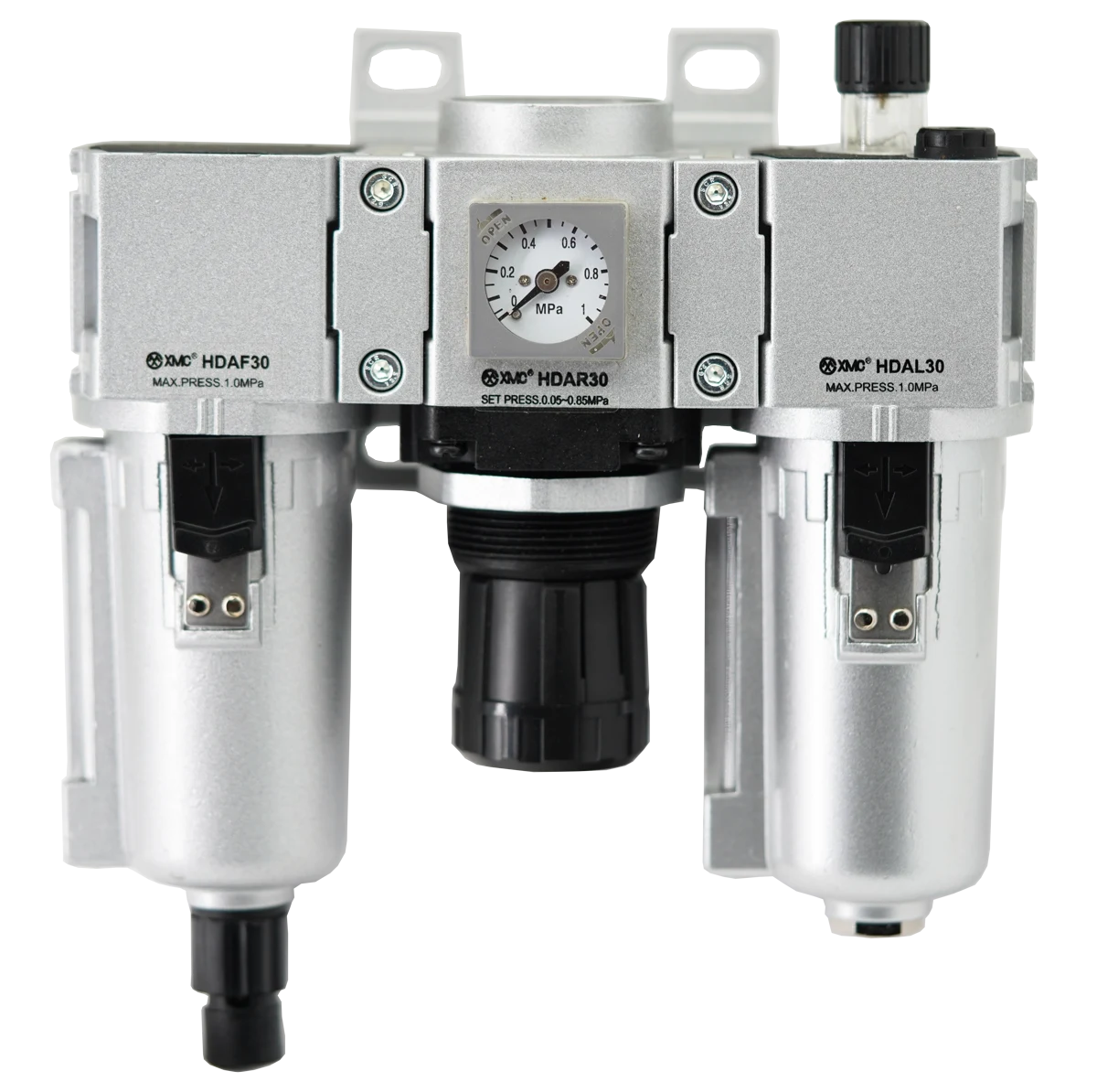
To size a pneumatic FRL, establish the air demand when connected devices operate together, the lowest available inlet pressure and the outlet pressure needed while air is flowing. Compare those conditions with the exact model's flow data, then confirm its port, thread and air-treatment options. A matching connection size or an idle gauge reading does not establish that the unit can supply the machine.
Start with the functions the machine actually needs
FRL means filter, regulator and lubricator. Decide whether the branch needs all three before comparing sizes. In the XMC HDA range, HDAC uses separate HDAF, HDAR and HDAL modules; HDAC-A combines an HDAW filter-regulator with an HDAL lubricator. Both include lubrication. For equipment requiring non-lubricated air, review a configuration without the lubricator against the specified air quality. [1] Filtration, pressure control and lubrication requirements determine the configuration to be sized.
Separate average consumption from simultaneous demand
List every air user supplied through the unit, including actuator branches, blow-off nozzles and vacuum generators. Record which ones overlap and for how long; Festo's system guidance highlights peak demand and these additional air consumers. [2] The example below assumes three flat flow demands, all using the same normalized reference conditions, operating together for one second in a ten-second cycle. Their combined demand is 720 L/min during that second, but only 72 L/min averaged across the cycle. Sizing from 72 L/min would ignore the operating window. These are illustrative inputs, not XMC ratings. Actual cylinder flow varies through a stroke, so measured traces or a suitable calculation may reveal shorter peaks.
| Air user | Assumed flow while operating | Timing in each 10-second cycle |
|---|---|---|
| Actuator branch A | 180 L/min | First second |
| Actuator branch B | 240 L/min | First second |
| Blow-off nozzle | 300 L/min | First second |
| Combined operating demand | 720 L/min | 720 x 1/60 = 12 litres per cycle |
| Cycle-average consumption | 72 L/min | 12 litres x 6 cycles per minute |
Keep flow units and reference conditions comparable
Copy the complete unit notation from the catalogue or instrument. The HDA regulator and filter-regulator graphs use L/min (ANR). [1] A reading described only as 'litres per minute' leaves its reference basis unclear. Ask whether a quoted flow is normalized or represents volume at the actual line pressure and temperature. When comparing SCFM, normal litres or ANR data, confirm the reference conditions before converting. Also distinguish average consumption from a rated flow measured at a stated pressure difference: identical units do not make those two quantities interchangeable.
Define the pressure requirement while air is flowing
Record the lowest expected pressure at the proposed unit's inlet during operation, rather than relying only on the compressor setting. Then define the pressure needed downstream during the critical movement. IMI Norgren identifies required flow, supply pressure and downstream pressure as selection inputs. [3] Keep the following pressure changes distinct. If the actuator is far from the FRL, include the intervening valve, fittings and tubing in the review. An acceptable pressure at the regulator outlet does not establish the same pressure at the actuator.
| Quantity | What is being compared | Selection implication |
|---|---|---|
| Filter differential pressure | Pressure immediately before and after the filter at a stated flow | Check the filter's applicable performance and condition. |
| Intended pressure regulation | Higher supply pressure and the lower downstream setting | This reduction is the regulator's function; it is not all an unwanted restriction. |
| Flow-related outlet droop | Outlet pressure at the same setting as demand increases | Use the regulator curve to check whether flowing pressure remains sufficient. |
Read the curve for the exact model and operating point
Identify the model, port and plotted inlet pressure first. On the HDA catalogue's HDAR and HDAW flow charts, the horizontal axis is flow and the vertical axis is outlet pressure. Solid and dashed lines represent inlet pressures of 1.0 MPa and 0.7 MPa respectively. [1] Locate the required flow and follow the relevant outlet-pressure curve to assess the pressure available. The right-hand limit of the graph is not a universal usable-flow rating. If the actual inlet pressure, port or configuration differs, request applicable data instead of treating the nearest graph as a verified match.
Use HDA body size and port size as separate selection fields
The XMC tables list both HDAR20-02 and HDAR30-02 with a 1/4-inch port; HDAW has the same overlap. Their body size is different, and the size-30 flow chart is labelled for a 3/8-inch connection. [1] Consequently, a 1/4-inch connection alone cannot identify the right body or justify using the size-30 chart for that port. The table below helps locate the relevant catalogue data; it is not a maximum-flow table. Confirm the thread standard and complete ordering code separately.
| Body size | Listed port sizes | Port on flow chart |
|---|---|---|
| 20 | 1/8 or 1/4 inch | 1/4 inch |
| 30 | 1/4 or 3/8 inch | 3/8 inch |
| 40 | 3/8 or 1/2 inch | 1/2 inch |
Check the assembled air path before confirming the size
A regulator-only curve does not rate a complete station with additional filters, a lubricator, isolation valves or couplings. Review the selected assembly and its connected pipework together. Festo recommends considering the complete pneumatic chain. [2] Define any allowance for planned extra users or supply variation from the actual project; there is no percentage stated here as a universal XMC sizing rule. After installation, verify pressure and machine operation during the intended simultaneous sequence. Follow the equipment's isolation and depressurization procedure before changing components or measurement connections.
Send a complete FRL sizing request to XMC
Include the machine application, air-treatment functions, required flow with units and reference conditions, demand timing, minimum operating inlet pressure and required downstream pressure. Add port size and thread standard, connection layout, mounting space, filtration and drain requirements, and whether lubrication is permitted or required. If flow is unknown, supply cylinder bore and stroke, target movement time, cycle sequence and the other connected air users. A model or drawing reference, quantity and destination help complete the inquiry. XMC can then review the candidate configuration against your operating data.
Catalogue and technical references
XMC model and chart details come from the HDA catalogue. The other manufacturers' references support general selection principles; their product ratings are not applied to XMC products. The demand worksheet is an illustrative calculation with stated assumptions, not a product recommendation.
Questions buyers ask.
Can I select an FRL from pipe size alone?
No. Connection size is one requirement. Check the exact configuration's flow performance at the available inlet pressure and required flowing outlet pressure. Different body sizes can share a port size.
Should I use average or peak air consumption for sizing?
Provide both, with the operating sequence and peak duration. The FRL must support the required operation when users overlap. A shift or cycle average can conceal short periods of much higher demand.
How much pressure drop is acceptable across an FRL?
There is no single value for every installation. Define the pressure needed downstream during operation, then review the selected assembly's characteristics. Separate intended pressure regulation from filter loss and flow-related outlet droop.
Is a larger FRL always the solution?
No. Check the complete supply path and the required treatment functions. Increasing the FRL body size alone may leave a restrictive coupling, undersized branch or inadequate upstream supply unresolved.
What if I do not know the required flow?
Send the actuator sizes, stroke and movement time, cycle timing, operating pressures and details of nozzles or vacuum generators. Identify simultaneous users so that an application calculation or measurement plan can be prepared.
Technical references
- [1] XMC Huayi catalogue, 21 June 2025 edition. HDA combinations on printed pages 48 and 50; HDAR specifications and flow charts on pages 54-55; HDAW specifications and flow charts on pages 58-59. Relevant pages visually checked on 29 September 2026.
- [2] Festo, Save compressed air costs and reduce energy consumption in pneumatics. Air consumers, peak demand and whole-system sizing. Accessed 29 September 2026.
- [3] IMI Norgren, What is a filter regulator? Selection by required flow, supply pressure and downstream pressure. Accessed 29 September 2026.
Put the guide to work.
Choose the relevant XMC series, download its product PDF and include the application details with your inquiry.