
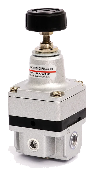
Choose an HIR manual configuration when the pressure setting will be adjusted at the regulator. For an air-operated configuration, specify the required main-air pressure and flow separately from the proposed pneumatic control source. Obtain the exact model, control-port drawing and operating requirements from XMC before ordering. A main supply-pressure requirement is not a pilot-pressure specification, and changing one digit in a manual model is not a confirmed selection.
Start with who changes the pressure setting
Write down where the pressure setting must be changed, who is allowed to change it and whether that setting stays fixed during production. A local hand adjustment and a pneumatic setting signal are different configuration requirements. The HIR ordering diagram distinguishes a basic handle setting from an air-operated setting. [1] IMI Norgren likewise explains the general distinction between a mechanical setting and air-pressure operation, including remote control. [2] That principle does not establish an HIR signal ratio or response time. Begin the inquiry with the required control task rather than selecting a precision label and adding control tubing later.
Read the HIR model table as configuration evidence
Printed page 77 gives separate standard and air-operated rows. For the manual HIR3000 body group it lists HIR3000-02, HIR3010-02 and HIR3020-02 with different set-pressure ranges. It also lists an air-operated HIR3120-02 row and an HIR4120 row with the final port field left to selection. [1] These are catalogue entries, not a complete quotation including thread, accessories and installation orientation. The table below records what is printed so the requested configuration can be checked against a current ordering sheet.
| Catalogue entry | Setting category and listed range | Main port entry | Quotation check |
|---|---|---|---|
| HIR3000-02 / HIR3010-02 / HIR3020-02 | Standard: respectively 0.01-0.2 / 0.01-0.4 / 0.01-0.8 MPa | 1/4 | Choose the required range, complete thread and accessories; the common body is not one fixed range. |
| HIR3120-02 | Air operated: 0.01-0.8 MPa | 1/4 | Confirm the current complete model and separate control-air requirements. |
| HIR4120, port field to be selected | Air operated: 0.01-0.8 MPa | 3/8 or 1/2 | Ask XMC to resolve the ordering-note inconsistency described below before ordering. |
Resolve the catalogue note before completing an air-operated code
The setting-type note on printed page 76 limits air-operated selection to HIR2 and HIR3000, while page 77 lists HIR3120 and HIR4120, and page 78 includes drawings of those two air-operated models. [1] These statements do not agree. Ask XMC for the current model-specific ordering information; do not use the note to invent an air-operated HIR2000 code or use the drawings alone to promise every HIR4000 option. A useful inquiry can identify the required function and the catalogue candidate while leaving the final supply code subject to confirmation. This is particularly relevant when replacing a unit whose label is incomplete.
Keep main supply, regulated output and control air separate
Provide a circuit sketch with three separately named items: the main supply, the controlled outlet to the load, and the proposed air-operated control connection. Page 78 has separate standard and air-operated drawings; the latter show an additional upper connection. [1] Obtain the exact connection identification, thread, permissible control-pressure range and required control-air quality for the proposed unit. The selection pages do not establish a universal one-to-one pilot/output relationship, a loss-of-signal state or a dynamic switching time. Do not infer those properties from another manufacturer's pilot regulator or from the main port size.
Use the minimum working-pressure column for the main supply review
In the page 77 table, the minimum working pressure is written as set pressure plus 0.05 MPa for the HIR2000 and HIR3000 standard groups and the HIR3120 row. The HIR4000 standard group and HIR4120 row state set pressure plus 0.1 MPa. [1] The column is headed minimum working pressure; it is not identified as the external control-pressure requirement. For example, applying the first expression to a hypothetical 0.20 MPa outlet setting gives 0.25 MPa. That arithmetic illustrates the table only. It does not select the pilot pressure or guarantee outlet performance at a particular flow. Send actual lowest inlet pressure and demand for review.
Specify the setting range, thread and viewing direction independently
The page 76 ordering diagram treats setting range, thread, accessories and installation direction as separate fields. It identifies an unmarked G thread selection, N for NPT and R for Rc in the thread field. A later R installation suffix concerns the reverse position of the gauge, bracket and label. [1] Do not decode a letter without its position. State the required thread in words as well as the complete code. Give the operator's viewing side, inlet/outlet direction, gauge readability and bracket arrangement. Confirm included gauge and bracket items in the quotation; a drawing of an optional accessory does not mean it is supplied.
Check the drawing and acceptance task for the chosen configuration
Use the drawing for the actual standard or air-operated model, rather than reserving space from the manual product photograph. Mark the adjustment or control-tube envelope, gauge viewing direction, mounting hardware and service access on the installation drawing. Ask for the model-specific vent and installation instructions as part of the technical review. Keep the pressure acceptance task equally specific: state the measurement point, required setting, permitted variation, inlet-pressure conditions and demand sequence. This article selects configuration information; the existing regulator comparison explains precision terms and the need for applicable performance data.
An inquiry worksheet for local adjustment or pneumatic control
Consider a hypothetical fixture where an operator sets one pressure before a production run. That task can start with a manual-configuration inquiry. If a different project needs the setting commanded pneumatically from another location, submit the control circuit as well as the load circuit for air-operated review. Neither scenario is an HIR application approval. Use the same load conditions in both quotations so the comparison does not confuse a change in operating duty with a change in setting method.
| Information | Manual inquiry | Air-operated inquiry |
|---|---|---|
| Setting task | Who adjusts the handle, access and required range | Where the pneumatic command originates, intended range and change sequence |
| Main air path | Minimum/maximum inlet, outlet requirement and operating flow | The same main supply/output data, separately from control air |
| Control details | Any setting-access or tamper requirements to confirm | Source, connection diagram, proposed signal conditions and required loss-of-signal behaviour for XMC confirmation |
| Installation and order | Complete model, thread, gauge, bracket and orientation | Confirmed current air-operated model, separate control-port specification, accessories and drawing |
| Acceptance | Where and under which demand conditions pressure is checked | The same outlet checks plus the requested command-change and signal-loss tests, subject to supplier instructions |
Catalogue and technical references
HIR model rows, ordering fields and drawings above come from the customer catalogue. The discrepancy between its setting note and model table remains a confirmation item, not a revised product specification. The external reference supports only the general idea of pneumatic setting control; its ratings, remote-control performance and installation requirements do not apply to HIR.
Questions buyers ask.
Does air-operated mean that the HIR is an electronic proportional regulator?
No electronic command or electrical interface is established by the cited HIR pages. Specify the pneumatic control task and obtain the exact model-specific connection and control requirements.
Can I use the minimum working-pressure formula as the pilot pressure?
No. The table labels that column minimum working pressure. It does not identify those expressions as external control-pressure specifications. Ask for the separate control-air requirements.
Can I make an air-operated HIR code by changing the setting-type digit?
Do not do that without a confirmed ordering sheet. The setting note and model table have an inconsistency, and the final model also needs its range, port, thread, accessories and orientation checked.
Are the HIR main port and gauge port the same connection?
They serve different purposes. The catalogue lists model-specific main ports and a G1/8 pressure-gauge port. Confirm the separate control connection on an air-operated version; a gauge port is not automatically a pilot connection.
Will an air-operated configuration hold a specified outlet tolerance during every cycle?
Setting method alone does not establish that result. Provide the permitted variation, flow, inlet-pressure range, command sequence and measurement point, and request applicable model data and acceptance instructions.
Technical references
- [1] XMC Huayi Pneumatic Catalogue, edition 21 June 2025, printed pages 76-78: HIR ordering diagram, standard and air-operated model table, and overall drawings. Original customer PDF and published extract visually checked 26 October 2026. The p76 setting-note conflict with p77/p78 is retained as a supplier-confirmation item.
- [2] IMI Norgren, How do Pneumatic Pressure Regulators work?: general pneumatic setting/control distinction and separate inlet, outlet and flow selection inputs. Read 26 October 2026. No Norgren rating or pilot/output relationship is assigned to HIR.
Put the guide to work.
Choose the relevant XMC series, download its product PDF and include the application details with your inquiry.