
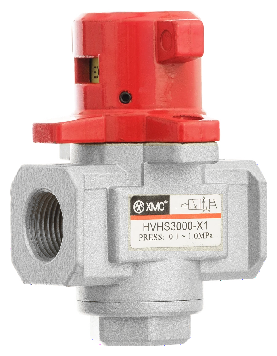
Select an HVHS venting lockout valve by its full connection code, separate supply/outlet and exhaust sizes, and installation drawing. The XMC catalogue shows manual three-port, two-position operation: one state connects supply P to outlet A; the other blocks supply and connects A to exhaust R. Confirm the lockable state and operating instructions with XMC, then review the complete machine circuit and pressure-verification requirements. A lock feature does not establish a machine-safety rating.
1. Start with the branch that must be isolated
An inquiry for a G1/4 lockout valve leaves several purchasing decisions unresolved. The HVHS range includes two body sizes with that connection, and their exhaust ports and dimensions differ. Start with a circuit sketch marking the intended isolation point, upstream supply and downstream equipment. Record working pressure, peak demand with its reference conditions, and the installed thread specification. This guide turns those inputs into a model-specific HVHS inquiry. It covers the documented HVHS2000-5000 range; it does not assign these data to another series or specify a complete machine isolation procedure. [1, 2]
2. Read P, A and R as three different connections
Printed catalogue page 80 labels P at the supply side, A at the downstream outlet and R at the exhaust. Its two-position symbol shows the connection states below. The drawing marks the two main connections as 2-G; use the table heading Vent size for the separate exhaust thread. The symbol identifies the component paths, not the air condition in every downstream branch. Ask for the operating instructions showing how the delivered control reaches each state and which state can be locked. Do not infer that sequence from a red handle or a product photograph. [1]
| State | Open path | Blocked path | Question for the selection review |
|---|---|---|---|
| Supply | P to A | R exhaust | Can the complete air path meet demand at the required downstream pressure? |
| Venting | A to R | P supply | Which downstream volumes communicate with A in the intended machine state? |
3. Compare full HVHS codes, not just the main port
The eight rows below are transcribed from the original dimension table on page 80. All sizes retain the catalogue G thread designation. Dimensions A and B are drawing references in millimetres; they are not a complete clearance specification. A matching main connection does not prove equal exhaust capability, available flow or installation fit. No flow curve or universal venting time is given on this page. [1]
| Full catalogue model | P/A connections | R vent size | A (mm) | B (mm) |
|---|---|---|---|---|
| HVHS2000-01-X1 | G1/8 | G1/8 | 40 | 59 |
| HVHS2000-02-X1 | G1/4 | G1/8 | 40 | 59 |
| HVHS3000-02-X1 | G1/4 | G1/4 | 53 | 78 |
| HVHS3000-03-X1 | G3/8 | G1/4 | 53 | 78 |
| HVHS4000-03-X1 | G3/8 | G3/8 | 70 | 84 |
| HVHS4000-04-X1 | G1/2 | G3/8 | 70 | 84 |
| HVHS5000-06-X1 | G3/4 | G1/2 | 90 | 136 |
| HVHS5000-10-X1 | G1 | G1/2 | 90 | 136 |
4. Resolve the G1/4 choice before issuing the order
HVHS2000-02-X1 and HVHS3000-02-X1 both list G1/4 main connections. The first has a G1/8 exhaust and A/B dimensions of 40/59 mm; the second has a G1/4 exhaust and A/B dimensions of 53/78 mm. This is a useful reason to put the full code on the purchase order. It is not proof that either valve meets a particular flow or pressure-release requirement. Send the required duty to XMC for review, including connected volume and the downstream valve states relevant to exhausting. If exhaust performance is critical, request applicable performance evidence and assessment conditions instead of estimating seconds from thread size. [1]
5. Reserve space for the handle and exhaust arrangement
Use A and B to start the layout check, then compare the complete page-80 drawing with the proposed panel or pipe assembly. Include handle access, space for the proposed lock, connected fittings and the exhaust arrangement. State whether an exhaust accessory or routed exhaust is required and ask XMC to confirm its suitability for the selected model. The vent-thread size alone does not specify an accessory or its effect on exhausting. The catalogue photograph shows an assembly example; it does not establish that every HA or HDA connector, orientation or installation location is approved for every HVHS. Submit the actual arrangement for confirmation. [1]
6. Specify what the lock must do
The catalogue identifies secondary-side pressure release and a locking function, and the public product record identifies manual three-port, two-position operation. [1, 2] Add the required locked state, lock arrangement, access and restart responsibilities to the inquiry. Request the exact operating and locking instructions, compatible lock dimensions and any required supporting documentation. Those details are not established by the page-80 selection table. Festo explains that pneumatic components must be evaluated in their application and that the machine manufacturer is responsible for safety evaluation and documentation. [3] Do not assign a performance level, safety category or machine certification from the product name, catalogue header or locking feature.
7. Keep venting, controlled filling and circuit verification separate
HVHS selection here concerns manual supply switching, secondary-side venting and locking. [1, 2] For a separate requirement for gradual pressure return, use the linked HAV soft-start guide and confirm its own model data. Do not copy HAV pressure, pilot or electrical values into an HVHS order. SMC's valve precautions specifically call for releasing residual pressure between the valve and cylinder where a three-position closed-centre or double-check arrangement is used. [4] Mark such sections on the circuit and have the machine designer define pressure-verification points, load protection and restart requirements. A vent path through this valve alone cannot establish that all machine pressure has been released. [3]
8. Send a model-specific HVHS inquiry
Use the following brief to obtain a reviewable quotation. Attach the marked circuit and available installation drawing. If a value is unknown, label it unknown and ask what measurement or document is needed. The quotation should confirm the complete model, supplied configuration and requested evidence before the valve is approved for the machine.
| Field | Information to send or confirm |
|---|---|
| Model and connections | Full HVHS code if known; P/A connection size and G thread requirement; R exhaust connection. |
| Duty | Available inlet and required downstream pressure; peak flow with units and reference conditions; connected volume and operating states. |
| Installation | Page-80 drawing references; marked available space; handle, lock and fitting access; proposed exhaust arrangement. |
| Locking and verification | Intended locked state; lock requirements; operating instructions; circuit verification and restart responsibilities. |
| Purchasing and evidence | Quantity, destination and requested delivery date; required technical documents and any application-specific safety evidence. |
Catalogue and technical references
The XMC extract supplies the HVHS connection symbol, features, complete codes and dimensions. The public XMC product record confirms the model range and manual operation. Festo and SMC are cited only for general system evaluation and residual-pressure considerations; their product ratings or certified functions are not assigned to HVHS. The catalogue extract is a selection reference, so request the applicable operating instructions where a required detail is absent.
Questions buyers ask.
Which HVHS models have G1/4 main connections?
The page-80 table lists HVHS2000-02-X1 and HVHS3000-02-X1. They have different exhaust sizes and A/B dimensions, so include the full model code rather than ordering by G1/4 alone.
Is the HVHS exhaust port the same size as the supply port?
Not always. For example, HVHS4000-04-X1 has G1/2 main connections and a G3/8 exhaust. Check the separate vent-size column for the exact code.
How long does HVHS take to release downstream pressure?
No universal venting time is provided on the reviewed catalogue page. Provide the connected volume, initial pressure, circuit state and exhaust arrangement, then request applicable performance evidence and verification conditions.
Does the locking feature prove a certified safety function?
No machine-safety rating is established by the locking feature or product name. Confirm the required function and documentation for the complete application, including the locked state and pressure-verification arrangements.
Can the catalogue tell me which padlock fits?
The reviewed page does not specify compatible lock dimensions or a detailed locking sequence. Request those instructions for the selected valve and check lock access in the installation drawing before ordering.
Technical references
- [1] XMC Huayi Pneumatic Catalogue, 21 June 2025 edition, printed page 80: HVHS2000-5000 title, P/A/R symbol, secondary-side release and locking features, eight complete codes, connection sizes and dimension table. The single-page scanned product extract and enlarged table were visually read on 26 October 2026; no text layer was available.
- [2] XMC public content snapshot, retrieved 26 October 2026: HVHS Series Venting Safety Lock-out Valve, /en/products/hvhs-venting-safety-lock-out-valve/. Manual three-port, two-position operation, approved HVHS3000-X1 photograph and four model profiles. PDF values were checked against the original table rather than inferred from the snapshot.
- [3] Festo USA, Safe pneumatics, https://www.festo.com/us/en/e/solutions/safety-and-sustainability/machine-safety/safe-pneumatics-id_4562, read 26 October 2026: components require evaluation in the application; machine manufacturer responsibility for safety evaluation and documentation. No Festo rating, certification or product specification is transferred to XMC.
- [4] SMC, 3/4/5 Port Solenoid Valve Common Precautions 1, release of residual pressure, https://ca01.smcworld.com/catalog/Clean-en/vq100_en/spdfdata/vq100_en_11sp.htm, read 26 October 2026: residual pressure between valve and cylinder requires release with three-position closed-centre or double-check arrangements. Used only for this circuit consideration, not as HVHS operating instructions or specifications.
Put the guide to work.
Choose the relevant XMC series, download its product PDF and include the application details with your inquiry.