
For a conventional single-rod, double-acting pneumatic cylinder, theoretical extension force is pressure multiplied by the full piston area. Retraction uses the smaller annular area after subtracting the rod area. With gauge pressure p in MPa and bore D and rod diameter d in mm: push force = p × πD² / 4; pull force = p × π(D² − d²) / 4, both in newtons. These simplified results assume the other chamber exhausts to atmospheric pressure and exclude friction; use them to start selection, then check the actual circuit and load.
Start with bore, rod diameter and pressure at the cylinder
Bore is the internal diameter of the cylinder barrel, not the outside diameter of the cylinder body or its air port. Rod diameter matters because the rod occupies part of the pressurized area during retraction. Use the drawing for the exact configuration: a double-rod, rodless or spring-return cylinder needs a different area or force assessment. For an initial single-rod calculation, record the bore, rod diameter and gauge pressure available at the driving chamber. The compressor setting or a regulator's idle reading does not establish that pressure during motion. SMC identifies piston area multiplied by operating pressure as theoretical output. [1]
Use consistent units in the force formula
Calculate full piston area A = πD² / 4 and rod-side annular area Aᵣ = π(D² − d²) / 4. Multiply the appropriate area by pressure. One MPa equals one N/mm², so MPa and mm² give newtons directly. When pressure is in bar, multiply bar × mm² by 0.1. Do not enter a reading of 6 bar as 6 MPa: 6 bar is 0.6 MPa. If working in inch units, psi multiplied by in² gives pounds-force. Keep one unit system throughout the calculation. Parker's engineering data separately identifies push force and the rod-area deduction for pull force. [2]
| Direction | Pressurized area | Force with p in MPa and diameters in mm |
|---|---|---|
| Extension / push | Full piston area | F = p × πD² / 4, in N |
| Retraction / pull | Piston area minus rod area | F = p × π(D² − d²) / 4, in N |
| Same pressure in both comparisons | Different effective areas | Pull force is lower for this single-rod arrangement |
Worked example: 50 mm bore at 0.6 MPa
Consider a hypothetical cylinder with a 50 mm bore and a 20 mm rod, supplied with 0.6 MPa gauge pressure in the driving chamber. Assume atmospheric pressure in the exhausting chamber and omit friction. These are calculation inputs, not specifications for an XMC product. Full piston area is approximately 1,963.5 mm²; rod area is 314.2 mm²; annular area is 1,649.3 mm². Multiplication gives approximately 1,178.1 N on extension and 989.6 N on retraction. The difference is approximately 188.5 N, even though the pressure is unchanged. Rounded values are shown below; calculations use unrounded areas.
| Input or result | Extension | Retraction |
|---|---|---|
| Bore / rod diameter | 50 mm / 20 mm | 50 mm / 20 mm |
| Driving gauge pressure | 0.6 MPa (6 bar) | 0.6 MPa (6 bar) |
| Effective area, rounded | 1,963.5 mm² | 1,649.3 mm² |
| Theoretical force, rounded | 1,178.1 N | 989.6 N |
| Friction and exhaust back pressure | Not deducted | Not deducted |
Account for exhaust back pressure and friction
During a real stroke, pressure in the exhausting chamber can oppose motion. For extension, the pressure contribution is cap-end gauge pressure × full piston area minus rod-end gauge pressure × annular area. Friction must then be considered separately. Because these areas differ, simply subtracting the two pressures and multiplying by the full bore area is not the same calculation. Valve flow paths, exhaust controls, tubing and cushioning affect the operating conditions; a static supply reading alone is insufficient. SMC discusses the effect of exhaust control on back pressure. [5] Festo's sizing reference distinguishes pressure-area force from friction. [3] Do not apply a universal efficiency percentage to every XMC cylinder. Request model-specific guidance and representative pressure and load information.
Use the result to shortlist a bore size
For a first-pass theoretical push calculation, rearrange the formula to D = √(4F / (πp)), using newtons and MPa. An illustrative 1,000 N requirement at 0.6 MPa gives approximately 46.1 mm before friction, back pressure or application margin is included. This does not establish that a 50 mm cylinder is suitable. Define the force the machine needs throughout the stroke, the minimum driving pressure and an application-specific margin, then compare actual catalogue sizes and operating limits. Pulling applications also require the actual rod diameter. A larger bore changes air demand and installation size; it does not by itself prove that the valve and air supply can meet the required cycle time.
Check the load direction, guidance and stopping conditions
A force number is not a complete machine selection. Separate process force from the force needed to accelerate the moving mass, overcome guide friction or work against gravity. A horizontal sliding load is not converted to a cylinder requirement merely by multiplying its mass by gravity. Check both stroke directions and the most demanding part of the cycle. Review mounting alignment, side loads, rod buckling at the proposed stroke and the energy that must be absorbed at the ends. Festo treats buckling as a separate selection check. [3] For vertical or suspended loads, have the machine designer assess load support, loss of pressure and protective measures; theoretical pneumatic force is not a load-holding safety rating. Observe existing instruments only under the machine's approved procedure. Installing instruments or servicing the circuit requires isolation, release of trapped pressure and secured loads.
Compare XMC cylinder families after defining the duty
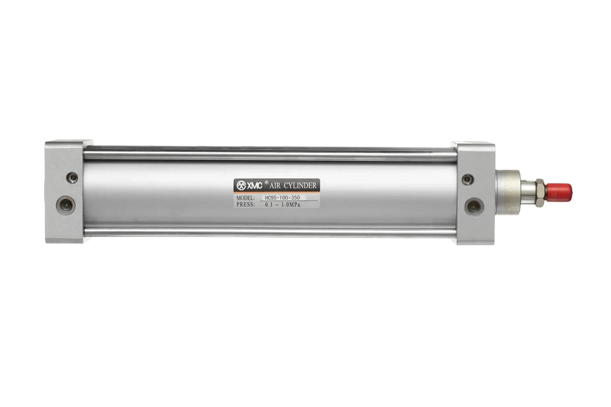
Use the calculation and machine requirements to organize a series review. XMC lists HC95 tie-rod cylinders, HMB pneumatic cylinders and HCQ2 compact cylinders; each linked product page provides its own catalogue PDF. [4] Compare the exact bore, stroke, rod configuration, mounting, cushioning and switch requirements. The shared pressure-area principle does not make dimensions, accessories or performance interchangeable. The pictured HC95 is a series illustration, not the 50 mm example. Ask XMC to confirm the complete ordering configuration and relevant drawing before placing an order.
Send a force and bore-size inquiry with operating data
A useful inquiry pairs the calculated force with the conditions behind it. If a value is unknown, mark it unknown and send the available drawing or operating description. Do not substitute an assumed rod size or a compressor nameplate pressure for missing application data. XMC can then review a proposed family and identify which dimensions or operating conditions still need confirmation.
| Item | What to send |
|---|---|
| Required duty | Push and pull force in N; process load; moving mass; horizontal or vertical motion |
| Cylinder configuration | Existing or proposed model, bore, rod arrangement, stroke and mounting drawing |
| Pressure conditions | Available pressure during the cycle, measurement location, units and any exhaust back pressure data |
| Motion and circuit | Target speed, cycle frequency, valve, tubing, flow controls and cushioning requirements |
| Environment and options | Air quality, temperature, exposure, switch requirements and available installation space |
| Procurement | Quantity, destination and requested delivery date for confirmation |
Technical references and calculation scope
The external references below explain general cylinder force and selection principles. Their product ratings, correction factors and ordering details do not establish XMC specifications. The worked example is calculated from the stated hypothetical inputs. Use the current XMC drawing and confirmed application conditions for a final selection.
Questions buyers ask.
What is the formula for pneumatic cylinder force?
Theoretical force is pressure multiplied by effective piston area. For a single-rod, double-acting cylinder with atmospheric exhaust, push force uses πD² / 4; pull force uses π(D² − d²) / 4. With pressure in MPa and diameters in mm, the result is in newtons. Friction and back pressure require additional assessment.
Why is cylinder pull force lower than push force?
At the same driving pressure and atmospheric exhaust, the rod reduces the effective pressurized area during retraction in a single-rod cylinder. The difference depends on bore and rod diameter. Do not apply this comparison unchanged to double-rod, rodless or spring-return designs.
How much force does a 50 mm pneumatic cylinder produce at 6 bar?
The theoretical push force is approximately 1,178.1 N at 6 bar, or 0.6 MPa, with atmospheric exhaust and no friction deduction. If the rod diameter is 20 mm, theoretical pull force is approximately 989.6 N. These illustrative calculations are not an XMC product rating or a permissible lifting load.
Does a larger port size increase cylinder force?
Port size does not change the piston area. Valve, tubing and port restrictions can affect the pressure and airflow available during a stroke, so they matter to actual operation and speed. Calculate force from the appropriate area and chamber pressure, then check the complete air path.
Can I choose a cylinder from load mass alone?
No. Selection also depends on motion direction, process force, acceleration, friction, pressure conditions, stroke, guidance and stopping requirements. Vertical loads additionally need an assessment of support and pressure-loss behavior. Send the load and duty information with the proposed model so XMC can review the application.
Technical references
- [1] SMC Corporation, Air Cylinders FAQ: theoretical output equals piston area multiplied by operating air pressure; accessed 20 October 2026.
- [2] Parker Hannifin, Pneumatic Actuator Products, catalogue 0900P-7, engineering data printed page A6: theoretical push/pull force, effective area and gauge-pressure units; accessed 20 October 2026.
- [3] Festo, Pneumatic Linear Actuators, Rotary Actuators, Grippers and Vacuum Components, printed pages 23–24: force/friction and buckling checks. Its table's friction assumption is not adopted as an XMC efficiency or universal margin; accessed 20 October 2026.
- [4] XMC Huayi Pneumatic 2025 Catalogue and published product records: HC95 printed pages 98–101, HMB 102–106, HCQ2 compact 107–108. Series identities and catalogue links checked on 20 October 2026; no competitor ratings are assigned to XMC.
- [5] SMC Corporation of America, Best Practices: Control Air Flow of Cylinders, pressure/area and force, airflow/speed and exhaust-control back pressure; accessed 20 October 2026.
Put the guide to work.
Choose the relevant XMC series, download its product PDF and include the application details with your inquiry.