
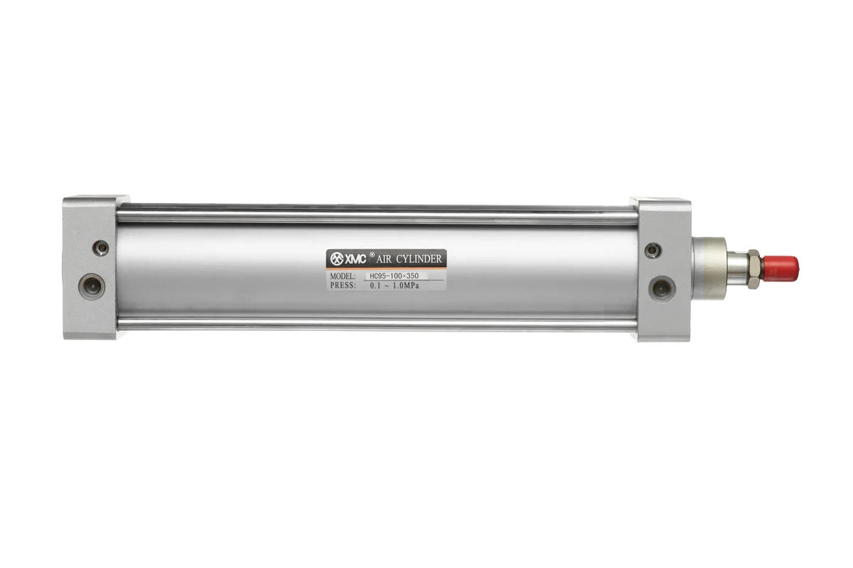
Specify the required movement and installation conditions first: load and direction, working pressure, stroke, available envelope, mounting, speed, cushioning and sensing. Then calculate or verify the required bore with an appropriate engineering margin and confirm the exact configuration in the product PDF.
Describe the motion and load
Record whether the cylinder pushes, pulls, lifts, clamps or positions, and note how the load changes during the stroke. Side load, impact and guidance should be handled by the machine design rather than assumed to be carried by the piston rod.
Define bore and stroke from the working conditions
Use the available working pressure and required force to determine a candidate bore, then include a suitable margin for pressure variation and mechanical losses. Stroke comes from the required travel plus the installation arrangement.
Check mounting, cushioning and sensing
Confirm the mounting style, rod-end connection, available space, expected speed, end-of-stroke cushioning and magnetic sensor requirement. These choices can change the ordering code and the overall dimensions.
Verify the exact series document
Compare the selected configuration with the HC95, HMB or HCQ2 product PDF. Send the intended bore, stroke, mounting, pressure, speed, load orientation, sensor requirement and quantity with the inquiry.
Questions buyers ask.
Is bore size determined by load alone?
No. Available pressure, force direction, mechanical losses, acceleration, safety margin and the machine arrangement also affect the choice.
What information is most useful when replacing an existing cylinder?
Send the old model number, bore, stroke, mounting dimensions, port size, sensor arrangement and clear photographs or a dimensioned drawing.
Technical references
- XMC Product Catalogue — 21 June 2025, printed pages 98–110.
Put the guide to work.
Choose the relevant XMC series, download its product PDF and include the application details with your inquiry.