
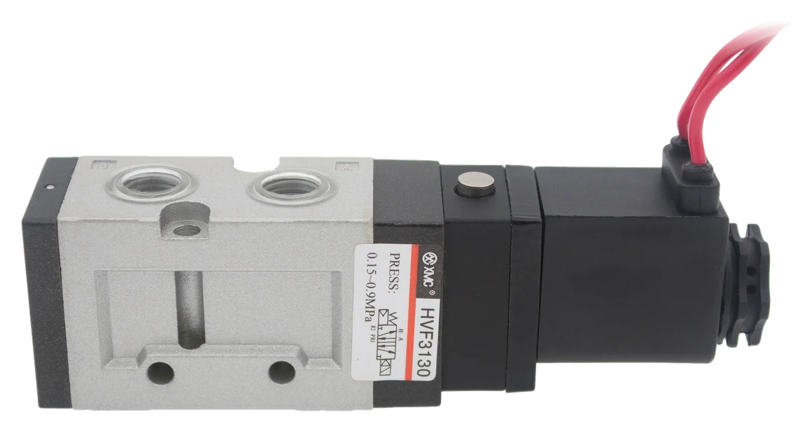
Select a pneumatic solenoid valve by the required switching function first, then check flow performance at the available working pressure, port and thread compatibility, and the complete electrical specification. Port size alone does not establish flow capacity. Match the coil's rated voltage, AC/DC supply, frequency where applicable and approved connector arrangement. For XMC HVF valves, send the complete ordering code or the cylinder and control requirements for a configuration review.
Start with the motion and valve function
For a double-acting cylinder, identify which chamber must receive air and which must exhaust in each step. A 5/2 directional valve provides five ports and two switching positions for this task. A 3/2 valve has one working port and is commonly used with a single-acting actuator. [2] The XMC HVF3000/5000 selection reviewed here is a two-position, five-port pneumatic range. [1] Keep this separate from a two-way fluid shutoff valve: the XMC HPU range is intended for air, water or oil flow control and requires a different application review. State the medium and circuit function before selecting by appearance or connection size.
Specify the return behavior as well as the coil count
For a typical 5/2 monostable valve, removing the command lets a spring or pneumatic return restore the rest position. A bistable version needs another command to change back. Check the circuit symbol and reset method: coil count alone is insufficient, because some two-coil valves return to a centre position. [2] XMC's HVF catalogue distinguishes single and double electric control. [1] Describe the required sequence after a command ends, after electrical power is lost and when air is restored. A retained spool position does not establish safe load holding. SMC's precautions note possible unexpected actuator movement when a double-solenoid valve is first used. [4] The machine's safety review must address startup and failure behavior independently of ordinary valve selection.
Do not treat port size as a flow rating
The HVF table offers a useful comparison: single-electric-control HVF3130 and HVF5120 both have a G1/4 option, but their listed effective section areas are 17.1 and 45 mm². [1] Matching threads therefore do not establish equivalent internal capacity. These areas are catalogue values, not L/min ratings; this guide does not convert them into a maximum flow or promise a proportional increase in cylinder speed. Use the table to identify candidates, then request applicable flow data for the complete model and operating conditions. Include the thread standard explicitly. A nominal 1/4-inch description alone does not confirm that the mating fitting is the specified G thread.
| Single-electric-control model family | Listed port options | Effective section area | Working pressure |
|---|---|---|---|
| HVF3130 | G1/8 or G1/4 | 17.1 mm² | 0.15 to 0.9 MPa |
| HVF5120 | G1/4 or G3/8 | 45 mm² | 0.15 to 0.9 MPa |
Compare flow under stated pressure conditions
Provide cylinder bore, stroke, required movement time, working pressure and cycle sequence. These inputs let the supplier assess demand during the movement; a cycle-average consumption figure can conceal a short period of higher demand. When comparing valve flow figures, record the inlet pressure, outlet pressure or pressure difference, and the normalization standard. For example, Festo's HE data sheet states its standard nominal flow conditions as 6 bar inlet, 5 bar outlet and normalization to DIN 1343. [3] Those conditions belong to that data sheet and are not asserted as XMC test conditions. Review the supply and exhaust paths, including tubing, fittings, silencers and shared manifolds, rather than assigning the whole circuit's performance to the valve alone.
Check the minimum operating pressure at the valve
For the HVF3000/5000 configurations on printed page 111, XMC lists 0.15 to 0.9 MPa for single electric control and 0.1 to 0.9 MPa for double electric control. [1] The lower limit matters as well as the upper one. Check pressure at the valve during the intended sequence and during startup; the compressor setting is not proof that the valve inlet remains within its range. If operation is required below the listed minimum, request a suitable configuration instead of assuming a different coil voltage will solve it. Keep proof or test pressure separate from the continuous working-pressure rating.
Match voltage, AC/DC supply and wiring together
Use the actual coil label, ordering code and electrical drawing. The reviewed HVF catalogue lists 110/220 V AC at 50 Hz and 12/24 V DC, with G for grommet leads and D for DIN connection. Its published ordering examples include HVF5120-4G02 for a single-electric-control, 220 V AC, grommet, G1/4 configuration and HVF5220-5D03 for a double-electric-control, 24 V DC, DIN, G3/8 configuration. [1] Copy and confirm the full code rather than changing a suffix by guesswork. Also check the control output's current capability, connector pinout, polarity where relevant and any indicator or suppression circuit. Equal voltage numbers do not make AC and DC assemblies interchangeable: approved rectifier or dual-rated arrangements, where available, must be confirmed for the exact assembly. [5]
| Ordering field | Code | Catalogue meaning |
|---|---|---|
| Standard voltage | 3 | 110 V AC; catalogue AC specification: 50 Hz |
| Standard voltage | 4 | 220 V AC; catalogue AC specification: 50 Hz |
| Standard voltage | 5 | 24 V DC |
| Standard voltage | 6 | 12 V DC |
| Connection | G | Grommet lead connection |
| Connection | D | DIN connection |
Confirm the installation and air-quality requirements
The reviewed HVF table specifies filtered compressed air, a 5 to 50 °C ambient and medium temperature range, and no lubrication required. [1] Confirm suitability for the actual environment, air treatment and mounting arrangement before ordering. Check clearance for connectors and service access, the required exhaust arrangement and the exact model's drawing. Do not interpret a catalogue dust-protection description as an unlisted enclosure or washdown rating. For replacement work, record the existing valve's complete label and circuit symbol along with photographs of the ports and wiring. Isolate electrical and pneumatic energy and release residual pressure under the machine's procedure before disconnecting components.
Prepare a complete solenoid-valve selection inquiry
Send the complete model if known, or use the worksheet below. For a replacement, include the nameplate and existing circuit diagram. For a new machine, explain the motion sequence and the required behavior when commands, power or air are removed and restored. The HVF catalogue values help shortlist a configuration; flow suitability and the complete electrical arrangement still need confirmation for the application. Include quantity and destination so XMC can review the selection and quotation together.
| Selection field | Useful information |
|---|---|
| Circuit and motion | Medium, actuator type, switching function, sequence and required reset behavior |
| Cylinder demand | Bore, stroke, movement time, cycle frequency and simultaneous users |
| Pressure and air treatment | Minimum and maximum valve-inlet pressure during operation; filtration and lubrication requirements |
| Mechanical connection | Port size, thread standard, tubing, manifold arrangement and available installation space |
| Electrical connection | Rated voltage, AC/DC supply, AC frequency, coil power/current, energized duration, control output and wiring/connector requirements |
| Quotation | Exact model or reference label, drawings, quantity and destination |
Catalogue and technical references
XMC-specific values and ordering examples come from the 21 June 2025 HVF catalogue, printed page 111. The other manufacturers' sources support general circuit and selection principles; their flow ratings, electrical tolerances and safety specifications are not applied to XMC products.
Questions buyers ask.
Can I choose a pneumatic solenoid valve from port size alone?
No. In the reviewed HVF catalogue, HVF3130 and HVF5120 both offer G1/4, but list different effective section areas. Check the switching function, applicable flow data, working pressure and electrical configuration as well as the thread.
Does a double-solenoid valve always return when power is removed?
No. Read the exact valve's circuit symbol and reset specification. Removing a command and restoring air are separate conditions to review. Coil count alone does not define the rest position or guarantee safe actuator behavior.
Can I connect a 24 V AC supply to a 24 V DC valve?
Do not assume compatibility from the voltage number. Use the exact assembly's approved voltage, AC/DC type, frequency and connector arrangement. A rectifier or dual-rated option must be explicitly specified by the manufacturer; it cannot be inferred from a similar-looking coil.
Will a larger valve always make a cylinder move faster?
No. The valve is one part of the air path. Supply capacity, pressure during motion, tubing, fittings, exhaust restriction and the actuator's load can also limit performance. Review the complete circuit against the required movement time.
Can a 5/3 closed-centre valve safely lock a cylinder in position?
Do not use that function alone as a load-holding or safety guarantee. Compressed air is compliant, and valves and cylinders can leak. Precise or safety-related holding requires an application-specific design and suitable components. [4]
Technical references
- [1] XMC Huayi Pneumatic 2025 Catalogue, 21 June 2025 edition. HVF extract printed pages 111-115; ordering examples, effective section areas, pressure ranges, electrical and air requirements on page 111 visually checked on 3 October 2026.
- [2] Festo, Pneumatic valves. Directional functions, monostable and bistable behavior. Accessed 3 October 2026.
- [3] Festo, On/off valves HE data sheet. DIN 1343 nominal-flow reference and 6/5 bar measurement conditions on printed page 4. Accessed 3 October 2026.
- [4] SMC, 3/4/5-Port Solenoid Valves: Precautions, page 1. Intermediate stops, leakage and startup behavior. Accessed 3 October 2026.
- [5] IMI Norgren, 82080 data sheet, page 2. AC/DC ordering options, frequency and rectifier arrangements. Accessed 3 October 2026.
Put the guide to work.
Choose the relevant XMC series, download its product PDF and include the application details with your inquiry.