
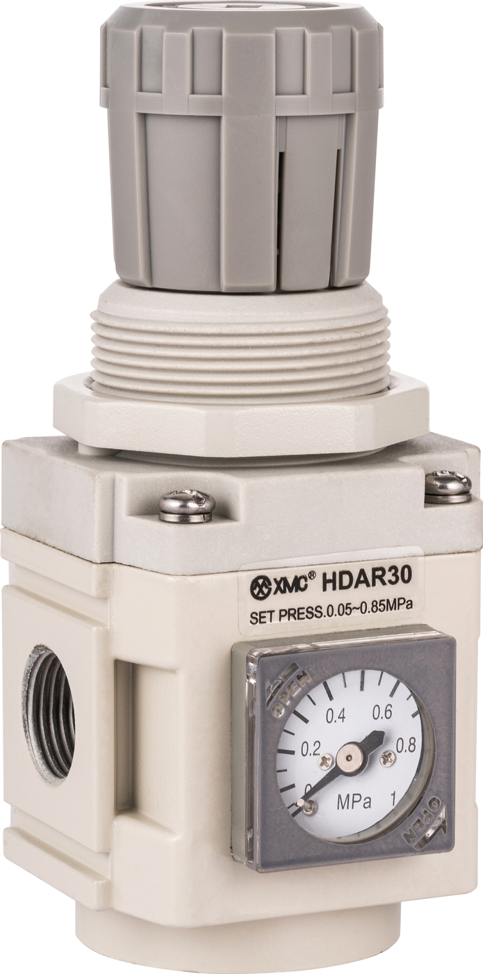
If air regulator pressure drops when a pneumatic cylinder moves, compare inlet and outlet pressure during that same stroke. Falling inlet pressure points toward the supply path or shared demand. A stable inlet with falling outlet pressure calls for checks around the regulator or filter-regulator and its flow capacity. Some regulator droop is normal; a moving gauge alone does not prove a failed component.
Why does pressure fall when the cylinder starts moving?
With the machine idle, little air may be flowing through the regulator. Opening a directional valve creates demand as a cylinder chamber fills. The regulator responds to downstream pressure changes by admitting more air. [2] Its flowing outlet pressure can be lower than the no-flow setting; the reduction associated with increasing flow is called droop. [3] A brief switching dip and a sustained pressure shortfall are different observations. Record the lowest pressure, how long it lasts and whether the machine still completes its required motion. There is no single acceptable drop for every pneumatic system.
Start with two pressure measurements
Use P1 immediately upstream of the unit and P2 immediately downstream. Record both before the stroke, during the troublesome movement and after recovery, keeping the regulator setting unchanged. Repeat the same cycle; simultaneous recording helps when demand changes quickly. A slow gauge can miss a short dip, so use suitable recording instruments when timing matters. These comparison steps help locate the affected part of the circuit; they are not a component pass/fail test. Before fitting instruments, opening a bowl or disconnecting tubing, have qualified personnel isolate and depressurize the circuit under the machine's approved procedure, including trapped pressure and supported loads.
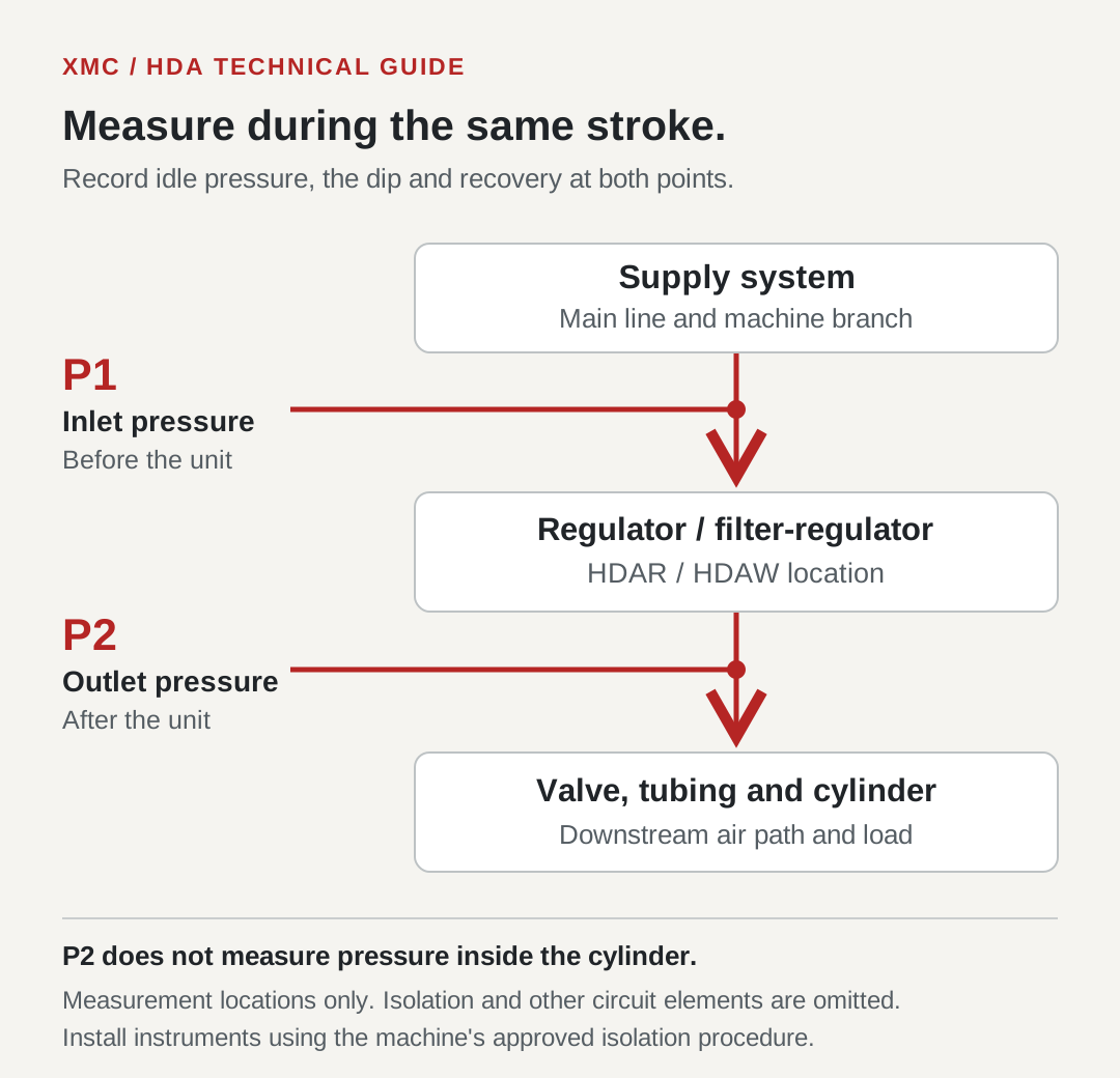
Use the readings to choose the next check
Treat the following patterns as starting points. More than one restriction or fault may be present. Compare the pressure trace with the machine event rather than replacing the regulator from a single idle reading.
| Observed pattern | What it suggests | Next check |
|---|---|---|
| P1 and P2 both fall | The unit is receiving a changing supply. | Check the branch supply, upstream valves and filters, and other users operating at the same time. |
| P1 stays steady; P2 falls as demand rises | The local unit may be limiting flow, or the change may be within its flow characteristic. | Check installation, filter condition where fitted, and the exact model's pressure-versus-flow curve. |
| P2 appears steady; one cylinder is slow or weak | The loss may be downstream, or the symptom may be mechanical. | Review the directional valve, tubing, flow controls, exhaust path and load; measure nearer the actuator if needed. |
| Pressure recovers between strokes but falls during overlapping movements | Peak demand may be greater than the shared path can supply. | Record simultaneous cylinders, blow-off nozzles and vacuum generators; review combined demand. |
| Outlet pressure keeps rising while there is no demand | This is a different symptom from flow-related droop. | Have the regulator and supply conditions assessed; do not apply this pressure-drop checklist as a diagnosis. |
Inspect the complete air path
A regulator works within a circuit of filters, valves, fittings, tubing and actuators. Festo's system guidance identifies leaks, kinked tubing and restrictions as maintenance concerns, and stresses sizing for peak demand. [4] Check whether an isolation valve is fully open, a hose has been crushed or a small-bore coupling has been added. Where a filter is fitted, inspect and service it according to its instructions. If possible, compare pressure across the suspected restriction while air is flowing. Increasing the set pressure can hide the symptom at one operating point; it does not establish that the restriction has been resolved.
HDAR or HDAW: identify the function and complete model
HDAR is the HDA pressure-regulator series; HDAW combines filtration and pressure regulation. The 21 June 2025 catalogue lists body sizes 20, 30 and 40 for both. [1] A shared port size does not establish equal flow performance. For example, the specification tables list a 1/4-inch port for both size 20 and size 30. Read the complete code, including gauge and other selected options, before requesting a replacement. For HDAW, also confirm filtration, bowl and drain requirements. A pressure loss measured across HDAW includes the filter-regulator assembly, not just the regulating mechanism.
| HDAR / HDAW body size | Listed port sizes | Port shown on flow plot |
|---|---|---|
| 20 | 1/8 or 1/4 inch | 1/4 inch |
| 30 | 1/4 or 3/8 inch | 3/8 inch |
| 40 | 3/8 or 1/2 inch | 1/2 inch |
Read the flow curve at your operating conditions
Pages 55 and 59 plot outlet pressure against flow in L/min (ANR), with inlet-pressure conditions identified by the line style. [1] Use the graph for the correct model and port, then check the outlet pressure available at the required flow and stated inlet condition. The rightmost number on the flow axis is not a universal usable-flow rating. Do not transfer the size-30 plot for a 3/8-inch port directly to a 1/4-inch version. Ask XMC for applicable performance data when the plotted configuration or conditions do not match your application. General regulator selection guidance likewise calls for checking both pressure requirements and the flow curve. [2]
Check peak demand, then verify the corrected cycle
Consider a hypothetical assembly station that works normally with one cylinder but slows when a second cylinder and an air nozzle operate together. The extra demand is a reason to measure, not proof that a larger regulator is the answer. Review the shared supply and local restrictions first. Average air consumption over a shift does not describe every short demand peak. After a justified correction, repeat the same measurements under the same operating sequence. Check motion, pressure recovery and the permitted working pressures before returning the machine to normal operation.
Send XMC the information needed for a selection review
Send the complete installed model code and a clear label photo, P1/P2 readings with the machine idle and operating, required working pressure, and the duration of the dip. Add cylinder bore and stroke, target stroke time or cycle rate, simultaneous air users, tubing internal diameter and length, and valve or coupling details. If flow is measured, include its units and reference conditions. State whether filtration is already provided or an HDAW combination is needed. These details allow the supply path and candidate unit to be reviewed together.
Catalogue and technical references
Model and graph details are taken from the XMC catalogue. Other manufacturers' references explain general regulator and compressed-air principles; their product ratings are not assigned to HDAR or HDAW. The measurement workflow above is an application troubleshooting guide, not a substitute for the machine's service instructions.
Questions buyers ask.
Does a pressure drop mean my air regulator is broken?
No. Some decrease with increasing flow is part of a regulator's characteristic. Check inlet pressure, actual demand, the applicable flow curve and machine performance before concluding that a component has failed.
How much regulator pressure drop is acceptable?
There is no universal percentage. The allowable change depends on the pressure needed for the machine's operation, the exact regulator and the flow conditions. A catalogue pressure range alone does not specify dynamic regulation performance.
Will changing from HDAR20 to HDAR30 solve the problem?
Only a selection review can establish that. First locate the loss and check peak demand. A larger regulator cannot correct every upstream restriction or downstream fault, and port size alone is insufficient for comparison.
Why is the regulator gauge steady while the cylinder is slow?
The gauge measures pressure at its own connection, not inside the cylinder. Check downstream valves, tubing, flow controls and exhaust conditions, plus the mechanical load. A slow gauge may also miss a brief pressure dip.
Technical references
- [1] XMC Huayi product catalogue, 21 June 2025: HDAR specifications and ordering on printed page 54, flow and pressure curves on page 55; HDAW specifications on page 58, curves on page 59. Visually checked 21 September 2026.
- [2] IMI Norgren, How do Pneumatic Pressure Regulators work? General operating principle and pressure/flow selection considerations. Accessed 21 September 2026.
- [3] Quincy Compressor, Droop. General definition of flow-related outlet-pressure reduction. Accessed 21 September 2026.
- [4] Festo, Save compressed air costs and reduce energy consumption in pneumatics. Whole-system sizing, peak demand, restrictions and maintenance. Accessed 21 September 2026.
Put the guide to work.
Choose the relevant XMC series, download its product PDF and include the application details with your inquiry.