
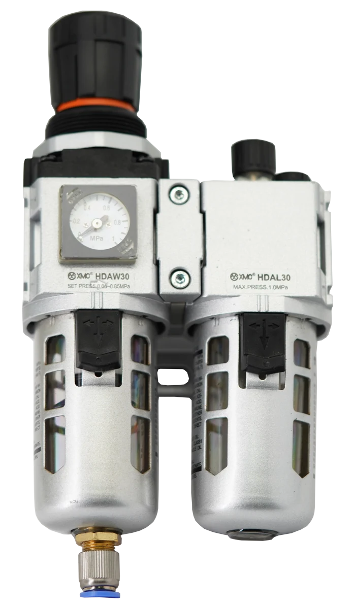
Before installing an FRL, confirm the required functions, complete model, flow direction, connection threads, mounting position and service space. Provide a suitable drain route and check whether downstream equipment needs lubrication. Commission under the machine's approved procedure, recording pressure both at rest and during demand. Use the exact product instructions for tightening, servicing and operating limits.
1. Confirm the assembly against the machine requirements
Match the delivery label to the approved bill of materials. Record the filter grade, regulator range, drain type, gauge and bowl configuration. HDA uses HDAF for filtration, HDAR for regulation, HDAW for combined filtration and regulation, and HDAL for lubrication. Three-piece HDAC and two-piece HDAC-A both include lubrication. [1] If the connected equipment calls for non-lubricated air, review a suitable arrangement without a lubricator rather than choosing by module count. Confirm inlet pressure, temperature and required flow before connecting the unit.
2. Plan isolation and pressure release before assembly
Have qualified personnel follow the machine's isolation procedure before connecting or servicing pneumatic components. Account for stored pressure, electrical controls and loads that could move when air is removed or restored. SMC's handling precautions require measures against dropping workpieces and unintended motion before equipment removal, followed by supply isolation and residual-pressure release. [3] Identify the isolation and pressure-verification points on the circuit drawing. A regulator turned down to zero is not, by itself, evidence that every downstream volume has been depressurized.
3. Check the airflow arrows and functional order
Trace the inlet and outlet on each delivered body. HDA combinations place filtration before regulation, then lubrication; a combined filter-regulator occupies the first two functions. [1] Norgren's B73G instructions likewise place the filter-regulator upstream of lubricators and require flow to follow the body arrow. [2] Confirm the approved layout for additional separators, valves and branches. Do not infer airflow direction from the gauge facing the operator or from a photograph.
4. Reserve mounting and maintenance space
The XMC HDA specification tables list vertical installation within ±5 degrees. [1] Check the actual mounting drawing, bracket position and fitted accessories before drilling the panel. Leave access to read the gauge, adjust the knob, inspect the bowl, operate the drain and remove service parts after depressurization. Route nearby cables and tubing outside that access envelope. Check the location for vibration, heat and exposure to chemicals against the chosen unit's material and environmental limits. SMC's precautions also identify these environmental checks and periodic bowl inspection. [3]
5. Match threads and keep connection debris out
Confirm the thread form as well as the nominal size; a matching size label alone is insufficient. Clean the piping before connection and prevent chips or sealing material from entering the air passage, as described in SMC's air-combination instructions. [4] Use the sealing method and tightening instructions appropriate to the actual connection. Request the XMC model-specific torque where it is not supplied; another brand's torque table is not a substitute. Support the piping so its alignment does not depend on forcing the FRL into place.
6. Identify the drain and route its discharge
Confirm whether the delivered unit drains manually, on air shutoff or automatically under its specified conditions. Those are different operating arrangements. The HDAW catalogue lists manual drainage for size 20 and air-shutoff drainage for sizes 30 and 40, with an automatic-drain option. [1] Plan where discharge will go and keep it observable for commissioning. Obtain the exact drain's tubing, pressure and routing requirements. Do not transfer a tube diameter from another manufacturer's manual to HDA. Add a drain inspection point to the maintenance handover.
7. Check lubrication only where the equipment requires it
Confirm the equipment manufacturer's lubrication requirement, oil specification and branch layout. The HDA combination tables list minimum oil-mist flows of 15 L/min for size 20, 40 L/min for size 30 and 50 L/min for size 40. [1] These are lubrication thresholds, not maximum assembly flow ratings. Check the lowest actual operating flow as well as peak demand. Norgren's lubricator guidance likewise treats flow and the connected equipment as selection factors. [5] Agree the oil-feed setting with the applicable instructions instead of applying a universal drops-per-minute rule.
8. Set pressure and verify the operating cycle
Before supplying air, check that bowls, fittings and gauge ports are secured according to their instructions. Set the regulator adjustment to the prescribed starting position and follow the machine's controlled startup procedure. Norgren instructs users to approach the desired pressure from below when adjusting its regulators. [2] Confirm the procedure for the installed model, then record inlet and outlet pressure at rest and during representative demand. Check leaks, drainage and any required lubrication during commissioning. Investigate a pressure shortfall before raising the setpoint.
9. Complete the installation handover record
Record the installed configuration and measured operating conditions so the next technician can compare like with like. Agree the inspection and service intervals using the applicable instructions and actual site conditions. A universal calendar interval is not established by the HDA selection catalogue.
| Record | What to capture |
|---|---|
| Identification | Full model and options, label photograph, circuit location and date |
| Connections | Thread form, size, airflow direction and approved assembly drawing |
| Operating check | Inlet/outlet readings at rest and under the recorded machine cycle |
| Drain and lubrication | Drain type, discharge route, observed operation and oil requirement if applicable |
| Service plan | Applicable instructions, spare-element identification, access and responsible person |
Catalogue and technical references
This checklist supports planning and handover. XMC model details come from its catalogue; the external references explain general installation principles. Their model-specific torque, drain dimensions and operating permissions do not apply automatically to HDA.
Questions buyers ask.
Can an HDA FRL be installed horizontally?
The HDA tables specify vertical installation within ±5 degrees. Follow the exact assembly instructions; do not apply another regulator family's mounting permission to an HDA assembly with filter or lubricator bowls.
Does a two-piece FRL mean no lubrication?
HDA's HDAC-A two-piece arrangement combines HDAW filtration/regulation with an HDAL lubricator. If lubrication is not required, select the needed functions explicitly rather than relying on the number of housings.
What tightening torque should I use for an HDA connection?
Use the instructions for the exact body, fitting and thread. If the supplied documents do not state it, request confirmation from XMC before installation. This checklist does not establish a universal torque.
Is an idle gauge reading enough to approve the installation?
Include a representative operating cycle. Record pressure during demand, check for leakage and confirm drain operation and any required lubrication. Retain the conditions and readings as the baseline for later service.
Technical references
- [1] XMC Huayi product catalogue, edition 21 June 2025: HDA combination, regulator and filter-regulator references on printed pages 48-59. Pages 48, 54 and 58 visually rechecked on 10 October 2026. Linked catalogue provides model-specific selection and dimensional information.
- [2] IMI Norgren, B73G installation and maintenance instructions: component position, airflow direction and regulator adjustment method. General principles only; no Norgren dimensions or torque values assigned to XMC. Accessed 10 October 2026.
- [3] SMC, Handling Precautions for SMC Products, F.R.L. units: isolation, residual pressure, environmental considerations and bowl inspection. Accessed 10 October 2026.
- [4] SMC, AC20-60-D air-combination operation manual: cleaning piping and preventing entry of sealing material. Accessed 10 October 2026.
- [5] IMI Norgren, What is a Lubricator? Flow and connected-equipment considerations. Accessed 10 October 2026.
Put the guide to work.
Choose the relevant XMC series, download its product PDF and include the application details with your inquiry.